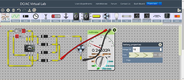
#CIRCUIT CODER TEST 3 CODE#
They're basically groups of code that run together. Without slowing down the program, the LED will only be turned off until the computer reaches the top of the loop again- less than 1/10th of a second later.įunctions are everywhere in programming. Why do you need the second delay? Because the loop() runs over and over again. To turn the LED off, you'll use digitalWrite() again with a LOW argument. The number you give to delay is measured in milliseconds, and 1000 milliseconds is one second. How much time? That's what the argument inside the delay() parentheses is for. There are no MIDDLE or MEDIUM commands.ĭelay() is a function that pauses your program for a set amount of time. digitalWrite also needs two arguments: pin number, and HIGH or LOW. In this loop, you use the digitalWrite() function to turn the LED on. You see them on line 5 of void loop occurs over and over again. PinMode commands happen between the curly braces that define the void setup(). You will learn more about the differences later. The first is the pin number, the second is whether that pin number should be used as an OUTPUT, INPUT, or INPUT_PULLUP. pinMode needs two arguments, or pieces of information, given to it. To do that in code, you use the pinMode() function. In this way, we can understand the entire truth table with toggling the three switches namely B1, B2 & B3, and the inputs are A0, A1 & A2.The first step in this program is to tell Maker Board which pin number holds the LED you'll light. When B2 is only pressed, A1 will be HIGH & Y2 will become LOW whereas remaining will be HIGH. When B1 is pushed, A0 will be HIGH & Y1 will become LOW whereas remaining will be HIGH. 74LS138 IC Logic DiagramĪfter connecting, if all switches are not pushed Y0 will be LOW & residual o/p will be HIGH shown in the above tabular form. Once the enable pins are connected, then the input line can be connected for getting the output. In the above tabular form, the first rows namely G1, G2 are the enable pins required to be connected correctly otherwise irrespective of all i/p, as well as o/p lines, will be high. The enable pins G1, G2A, and G2B, where G2=G2A + G2B. In the above tabular form, the H-HIGH, L-LOW and X- don’t care. For a better understanding of this concept, let us understand the following truth table. Here three buttons signify three i/p lines for this device. Here we have used a single device so the connections of G2A, as well as G2B pins, are connected to GND followed by linking G1-to-VCC for activating the chip. In the above circuit, the outputs are allied toward light emitting diode to illustrate which o/p-pin goes LOW & outputs of the IC are inverted. To understand the IC working, let us design a simple circuit with few required basic electronic components as shown below. Operating temperature is from -40✬ to +125✬.Integrates 3-enable pins for simplifying cascading.

This IC is particularly designed for high-speed.The features of the 74LS138 IC include the following.

The IC 74LS138 is a 16-pin integrated circuit, and each pin of this IC is discussed below. And also the inputs of this IC is clamped with Schottky diodeswhich are the high performance to contain line ringing as well as system design simplify. This IC is mainly used in de-multiplexingapplications with the help of an enable pin like a data input pin. The implementation of 24 line decoder can be done without using outside inverters, as well as a 32-line decoder needs a single inverter This IC includes three enable pins (where two pins are active low and one is active high) decreases the necessity of outside gates. These ICs can be used for minimizing the system decoding effects in memory systems with high performance. This IC is mainly used in applications like memory decoding with high performance otherwise data routing, etc.

The setup of this IC is accessible with 3-inputs to 8-output setup. The main function of this IC is to decode otherwise demultiplex the applications. The IC 74LS138 is a 3 to 8 line decoder integrated circuit from the 74xx family of transistor-transistor-logic-gates.


 0 kommentar(er)
